Marshall Field Monumentation Testing
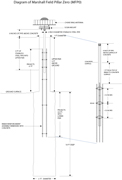
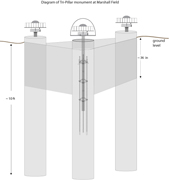
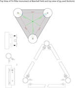
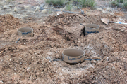
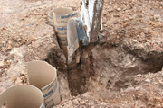
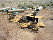
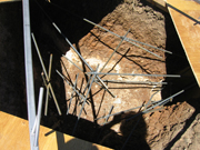
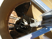
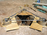
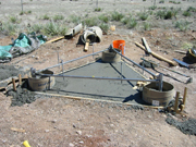
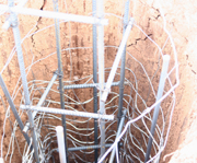
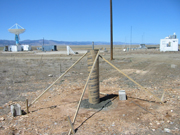
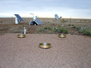
A single concrete (12 inch tube) pillar and a triangular concrete pillar with three marks/mounts were constructed for the test facility. The triangular pillar consists of three 12 inch tubular pillars joined together at the top with concrete and rebar. The triangular section extends one meter below ground and is anchored in the consolidated soil/clay, with roughly two inches protruding above ground. The top of the triangular concrete pillar was then covered with pea-gravel for water drainage and multipath mitigation.
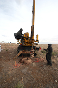
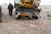
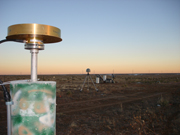
The triangular pillar design was chosen to investigate effects of equipment changes (antennas, antenna height, the addition and removal of radomes etc.) in a controlled, uniform, and fixed triangular system. The design can be installed at field sites with few modifications. The three marks were installed as a true triangle using a stainless steel jig to ensure proper alignment during the pouring of the concrete. SCIGN mounts are used on each of the three schedule 40, stainless steel pipes (located at each corner). There is also a steel pin located in the geometric middle of the triangular pillar with a 5/8" thread at the top for easy installation of most GNSS antennas. The diagrams and photos below show the installation of these monuments. The single concrete tubular pillar was installed about 60 meters to the north, north-west, and will be used to investigate monument stability and data quality of such constructions in consolidated soil.
Click on thumbnail for larger image
 |
 |
 |
 |
 |
 |
 |
 |
 |
 |
 |
 |
 |
 |
 |
 |
Last modified: 2019-12-24 02:13:00 America/Denver
)